
Blog
Do you need a voltage divider on the HC-05? Both sides of the argument are right
Troniction

You are wiring an HC-05 to an Arduino, you have read four tutorials, and two of them put a pair of resistors between the Arduino's TX pin and the module, while the other two run a plain wire and say the resistors are unnecessary fuss. The comments underneath both are full of people insisting the other lot are wrong.
They are both right. The divider is needed on one of the two data wires and not on the other, and almost nobody says which, so the two camps argue past each other for ever. The rule, in one line:
Arduino
TX→ moduleRXD: fit the divider. ModuleTXD→ ArduinoRX: do not.
That asymmetry is not a convention or a matter of taste. It falls out of two numbers, and once you have seen them the argument stops being interesting.
First, work out which wire you are asking about
Thirty seconds, before any resistor goes anywhere near the breadboard. Follow the wire with a finger and name the direction, because the whole answer depends on it.
| The wire | Which way the 5V problem runs | What it needs |
|---|---|---|
Module TXD into Arduino RX | Nothing crosses a boundary — 3.3V into a 5V input | A plain wire |
Arduino TX into module RXD | 5V into a 3.3V input | The divider |
TX means this pin talks. So the module's talking pin has to land on the Arduino's listening pin, and vice versa — the two wires cross. If you have wired them straight through, TX to TX, nothing breaks and you get nothing, for ever, with no error to explain it. That is worth ruling out before you go anywhere near the resistors, because it looks identical to a wiring problem the divider would fix.
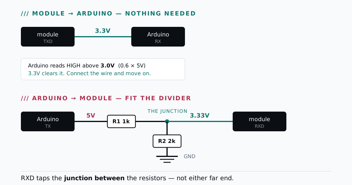
Direction one: module TXD → Arduino RX, connect it directly
Here is the arithmetic that settles this half.
The Arduino's input needs to see at least 0.6 × 5V = 3.0V before it will call a signal HIGH. That number comes from the ATmega328P's datasheet and it is not a guideline; it is the threshold the silicon uses.
The module drives 3.3V.
Three point three clears three. Every bit lands, with margin, using a plain jumper wire. There is nothing to buy, nothing to build, and no reason to be nervous about it. The people telling you the divider is unnecessary have almost always got this direction in mind, and for this direction they are simply correct.
Direction two: Arduino TX → module RXD, fit the divider
Now run it the other way and the numbers change completely.
The Arduino drives a full 5V into an input designed for 3.3V. The module's absolute maximum on that pin sits barely a tenth of a volt above its normal high, so you are not comfortably inside the specification with a little headroom — you are past the edge of it, on every single bit you transmit.
This is the direction the divider exists for, and it is the direction the other camp has in mind. They are also simply correct.
Both halves of this are about one pin, not about the module. People generalise the answer they got — "I never used resistors and mine works" — into a rule about HC-05s. It is not a rule about HC-05s. It is a rule about a 5V output meeting a 3.3V input, and it applies to exactly one of your four wires.
Why so many people say you do not need it
This is the part that keeps the argument alive, and it deserves an honest answer rather than a lecture, because the "you do not need it" camp is reporting a real experience.
They did not fit it, and their module still works.
Two things make that common. Most breakout boards put some protection on that input, and a great many of these modules tolerate 5V on RXD indefinitely without complaint. So the direct connection works, is reported as working, and becomes the advice in the next tutorial.
What you do not see are the ones that did not survive, because a module killed this way does not announce itself. There is no smoke and no heat. It simply stops accepting what you send. Very often it still powers up, still advertises, still pairs with the phone — and simply never acts on a single byte, which looks exactly like a software problem and sends the owner off to debug their sketch. Eventually they conclude the module was faulty, buy another, wire it the same way, and often get away with it the second time.
Two resistors cost a few cents. Fit them.
Building it
Two resistors, in the ratio 1 : 2. Either of these pairs gives you the same result:
R1, from Arduino TX to the junction | R2, from the junction to GND | Output |
|---|---|---|
| 1 kΩ | 2 kΩ | 3.33 V |
| 10 kΩ | 20 kΩ | 3.33 V |
The arithmetic is worth seeing once, because it is what makes the ratio the only thing that matters. A divider hands the module the fraction of the input voltage that R2 represents out of the total: R2 divided by R1 plus R2. With 1 kΩ and 2 kΩ that is two thirds, and two thirds of 5V is 3.33V. With 10 kΩ and 20 kΩ it is two thirds again, and the answer is identical. The resistors only ever divide the voltage in proportion to each other, which is why a pair ten times larger lands on exactly the same number.
The ratio is what matters, not the exact values. Anything in the same proportion, from a few hundred ohms up to a few tens of kilohms, behaves the same way here. No 2 kΩ in the kit? Two 1 kΩ resistors in series make one. No 20 kΩ? Two 10 kΩ in series.
Wire it in this order:
- Arduino
TXgoes into one end of R1. - The other end of R1 joins one end of R2. That joint is your 3.3V point.
- The far end of R2 goes to
GND. - Module
RXDconnects to the junction between the two resistors — not to either resistor's far end.
Step 4 is the whole trick, and it is the step people get wrong. The module's RXD does not go on the end of R1 and it does not go on the end of R2. It taps the point where the two meet. Put it anywhere else and you have either a plain 5V wire with two decorative resistors attached, or a pin tied to ground.
Only one direction needs this. Fitting a divider on the other line — module TXD into Arduino RX — is not dangerous, but it is pointless, and it can break a link that was working. That signal is 3.3V against a 3.0V threshold, which is only 0.3V of margin. Divide it and you drop under the threshold, and a connection that worked yesterday goes silent today. One divider. One direction.
The mistake that actually kills these modules
While we are on the subject of what damages a Bluetooth module, it is worth correcting a piece of folklore that circulates alongside the divider argument: that swapping VCC and GND instantly destroys the module.
That is overstated. Many of the common breakouts — the JY-MCU boards in particular — carry reverse-polarity protection and survive it. Do not treat it as safe, but do not assume a module is dead because it was briefly in backwards.
The failure that is documented as fatal is over-voltage on the supply. These modules are specified for 3.6–6V, and above 7V destroys them. So the Arduino's 5V pin is comfortably inside spec, and a 9V battery straight onto VCC is not.
Which raises the other wiring question people arrive with at the same time as this one:
Power the module from the Arduino's 5V pin, not its 3.3V pin. That is not overvolting it. Every one of these modules is sold on a breakout board with its own 3.3V regulator, and that regulator exists precisely to take 5V in and make clean 3.3V for the radio. Meanwhile the Uno's 3.3V pin is rated for 50 mA in total, against close to 40 mA while the module is advertising — which is why so many modules never appear in the phone's list at all.
How to tell whether the input is already damaged
If you have been running a direct 5V line for a while and you have started to worry, there is a straightforward test. Ask the module something and see whether it answers.
Put it into AT command mode and send a bare AT. If it replies OK, its receive path is alive — your command travelled down exactly the wire you are worried about and was understood. A module that still powers up, advertises and pairs, but never answers and never acts on anything you send, is the classic signature of a burnt RXD input.
If nothing comes back, do not conclude the worst immediately: a far more common reason for total silence in command mode is that one dropdown is set wrongly, and it produces exactly the same symptom on a perfectly healthy module. Rule that out first. Replace the module only when the line ending, the baud rate and the command syntax are all right for the part you are holding and it still will not answer.
The checklist, before you apply power
Every item here has cost somebody an evening, and none takes more than a few seconds.
VCCis on 5V, not 3.3V, and not on a data pin.GNDis connected — and if the module has its own supply, that ground is tied to the Arduino's ground as well.TXDandRXDcross: module TX to Arduino RX, module RX to Arduino TX.- The divider is on the Arduino-TX side only, with the module's
RXDon the junction. - Nothing else is sitting on pins
0and1if you are using the hardware serial port. - You have looked at the board once more before switching on.
Power it up and you should get a blinking LED — fast and continuous means it is advertising and waiting for something to connect.
That common-ground item deserves its own sentence, because it is the one that produces the strangest symptoms. Serial is a voltage measured against ground. Two circuits whose grounds are not joined have no shared idea of what zero is, and every byte becomes noise — which looks like a baud problem, or a broken module, or anything except the missing wire that it is.
Every other symptom in this subject sorts the same way, by which part of the chain is misbehaving, on the Arduino Bluetooth fixes index.
Common questions
- Does the exact resistor value matter, or only the ratio?
- Only the ratio, which is 1:2. A 1k with a 2k gives 3.33V and so does a 10k with a 20k. Anything in the same proportion from a few hundred ohms to a few tens of kilohms behaves the same here, so use what is already in your kit. If you have no 2k, two 1k resistors in series make one.
- My module has run on a direct 5V line for months. Is it damaged?
- Probably not, and that is exactly why this argument never ends. Most breakout boards put some protection on that input and a great many modules survive 5V indefinitely. But the ones that do not die quietly — they simply stop answering — so a module that has worked so far is evidence about your module, not about the practice.
- Should I fit a divider on the module's TX line as well, to be safe?
- No. It is not dangerous, but it is pointless, and it can break a link that was working. The Arduino reads anything above 3.0V as a high and the module already drives 3.3V, so there is only 0.3V of margin to give away. Divide that line and you can drop the signal under the threshold. One divider, one direction.
- How do I tell whether I have already damaged the module's input?
- Ask it something and see whether it answers. Put it into AT command mode and send a bare AT — if it replies OK, its receive path is alive, because your command reached it. A module that still advertises and pairs but never acts on anything you send is the classic signature of a burnt RXD input.
- Do I need the divider if I am using an ESP32 or another 3.3V board?
- No, because the problem the divider solves does not exist there. The divider is only ever about a 5V output driving a 3.3V input. If your board's logic is already 3.3V then neither direction crosses a voltage boundary and both wires connect directly. The rule is about the voltages, not about the module.
Still not connecting?
Arduino Bluetooth — Make It Connect is 62 pages of every way the link fails, why, and the fix — HC-05, HC-06 and HM-10 BLE, including the clone family almost nothing covers. $9.