
Learn
Why your Bluetooth breakout has its own regulator — and why 5V is not overvolting it
Troniction
One sentence keeps people on a power rail that cannot support their module:
The radio runs at 3.3V, so I should feed it 3.3V.
It is a reasonable inference. It is also the wrong one, and the reason is a distinction that almost nothing makes explicit: the module and the board it is mounted on are not the same thing.
Two different objects, one name
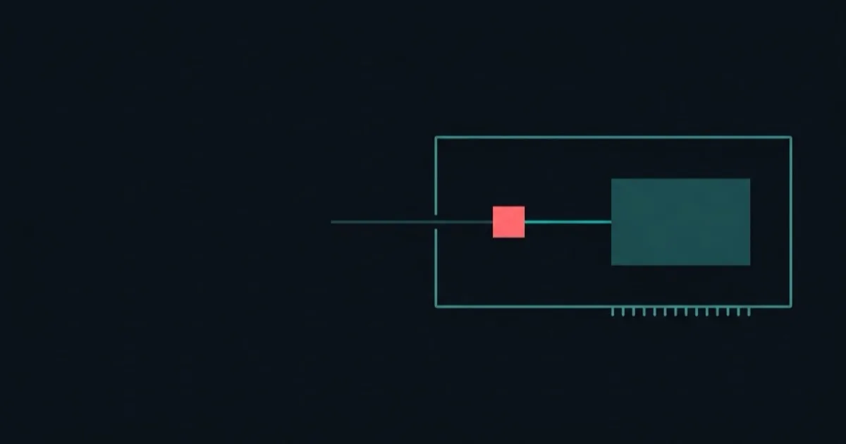
Look closely at an HC-05, HC-06 or HM-10 as they are actually sold, and there are two boards stacked together.
The module is the small rectangle with a metal can and a zig-zag antenna trace printed at one end. That is the radio, and it genuinely does run at 3.3V. Its datasheet says so.
The breakout board is the larger green board underneath, with the pin header you plug your jumpers into. It exists because a bare module is not usable by hand: its pads are tiny, it has no header, and it wants a supply most hobby boards do not conveniently provide.
So the breakout adds the missing pieces. A pin header. A status LED. Sometimes a button. And — the part that matters here — its own 3.3V regulator.
This is why the datasheet voltage and the pin you actually touch can disagree without either being wrong. The datasheet is usually describing the bare radio. The header belongs to the board.
What that regulator is for
The regulator's entire job is to accept a higher input voltage and produce clean, steady 3.3V for the radio behind it.
Which means feeding the board 5V is not a workaround, or a tolerated abuse, or something that works because the part is forgiving. It is the input the board was designed to receive. The regulator is sitting there doing the job it was put there to do.
Feeding the board 3.3V instead does not remove a step. The regulator is still in the path — it just has almost nothing to work with, because a regulator needs some voltage difference across it to regulate at all.
The real limit, which is at the other end
None of this means voltage does not matter. It does, and the boundary is worth knowing exactly.
| Supply | What happens |
|---|---|
| Below 3.6V | Under the specified range — unreliable |
| 3.6V to 6V | The specified operating range |
| 5V, from an Arduino | Comfortably inside it |
| Above 6V | Past the quoted range — and past the 662K regulator's rating |
There is no single figure for what kills one of these boards, because it depends on the regulator fitted. The small three-pin part many carry — marked 662K, an XC6206 — is specified for a 6V maximum input, so anything past the quoted range is already past the part. Boards built around the larger AMS1117 are rated to an absolute maximum well above that. You cannot tell which you have from the listing, so treat 6V as the line.
Compare that with the thing people actually fear. Five volts is not near the edge. Nine is outside every quoted range. The gap between those two is where the entire anxiety lives, and it is misplaced — it is aimed at 5V when it belongs to 9V.
Why this matters more than it sounds
If it were only a tidiness question, the 3.3V pin would be fine and this would be a footnote. It is not, because of a second number.
The Arduino Uno's 3.3V pin supplies 50 mA in total, for everything connected to it. A Bluetooth module draws close to 40 mA while advertising — the state it has to be in before your phone can discover it.
Forty against fifty, on a load that draws in bursts, is not headroom. The rail sags, the module resets, and it never stays alive long enough to appear in the phone's list. That is the most common reason a perfectly good Bluetooth module looks dead.
So "use the 3.3V pin because the radio is 3.3V" does two things wrong at once. It bypasses a regulator that was put there deliberately, and it puts the module on the one rail on the board least able to feed it.
Try both pins on the rail budget — the verdict flips the moment VCC moves.
How to check what you have
Not every board in this family is identical, and the clone situation makes labels unreliable. Two checks settle it.
- Look for the regulator. A small three-pin component near the
VCCpin, usually with tiny printed text, is the regulator. Almost every board sold with a pin header has one. - Read the silkscreen. Many of these boards print their accepted range directly next to the header — commonly something like
3.6V-6V. If the board says it, believe the board over a tutorial.
If a board genuinely has no regulator, it is a bare module on a breakout with only a header, and 5V is not safe for it. Those exist, they are uncommon, and they generally say so.
The question this is often confused with
Supplying the board and driving its logic pins are two different questions, and conflating them is the second most common mistake here.
VCC is handled by the regulator, as described above. The RX pin is not necessarily. It is an input to the radio, and on many of these boards it goes to the module with nothing in between — which means an Arduino sending 5V logic into it is a separate decision with a separate answer.
That is why you will find guides insisting on a resistor divider on RX and others reporting that they never used one and nothing broke. Both groups are describing real experience with boards that differ. The safe habit is to divide the RX line down unless you know the specific board tolerates 5V logic, while still feeding VCC the 5V it asks for. The two are not in tension.
Why the boards vary at all
There is no single manufacturer here. The HC-05 and HC-06 have been produced by many vendors for over a decade, and the HM-10 has been copied repeatedly — CC41-A, AT-09, MLT-BT05 and outright fakes, often sold under the original name in the same listing at the same price.
What tends to stay constant is the four pins and the wiring. What varies is firmware, which AT commands exist, what they answer, and occasionally whether a protection component that a tutorial assumes is present actually is.
This is a good reason to trust what is printed on the board in front of you over a number copied from a tutorial about a board someone else had. The silkscreen was printed by whoever made the thing you are holding.
One practical consequence: when a tutorial and your board disagree, the board wins. A tutorial was written about one specific piece of hardware that the author had in front of them, and the family has drifted since. The silkscreen, the regulator you can see, and the range printed next to the header all describe the object actually on your desk.
The transferable idea
This pattern is everywhere once you notice it. A sensor rated for 3.3V, sold on a board with a regulator and level shifting, that takes 5V happily. A display whose controller is 3.3V on a board built for 5V input. In each case the datasheet describes one thing and you are holding another.
Read the board, not just the chip on it. The pins you touch belong to the board, and what the board accepts is frequently more generous — and more deliberate — than the part number suggests.
Common questions
- Should HC-05 VCC go to 5V or 3.3V?
- 5V, in almost every case. The module is mounted on a breakout board carrying its own 3.3V regulator, so 5V is what the board expects. The Arduino Uno's 3.3V pin supplies only 50 mA in total, which is not enough headroom for a module drawing close to 40 mA while advertising.
- Will 5V damage my HC-05?
- No. These modules are specified for a supply of 3.6-6V, so 5V sits comfortably inside the range. How far past that is fatal depends on which regulator your board carries — the common 662K part is rated for 6V maximum input, while boards using an AMS1117 tolerate far more. A 9V battery wired straight to VCC is outside every quoted range.
- What is the difference between the module and the breakout board?
- The module is the small metal-canned radio. The breakout is the larger board it is soldered to, which adds the 3.3V regulator, the pin header, the status LED and sometimes a button. Datasheet voltages often describe the bare radio; the pins you touch belong to the board.
- Does the RX pin need a voltage divider even on 5V?
- That is a separate question from VCC, and the answer differs by module. Supplying 5V to VCC is handled by the onboard regulator; the logic pins are not necessarily protected the same way.
Still not connecting?
Arduino Bluetooth — Make It Connect is 62 pages of every way the link fails, why, and the fix — HC-05, HC-06 and HM-10 BLE, including the clone family almost nothing covers. $9.