
Build a Car With Your Kid · Chapter 7
Stage B1: the motor wires, steps B1 to B17
The video
The video of steps B1 to B17 isn’t filmed yet. It’s on its way, and it will go on this page: the QR in your book stays the same.
Until then, here are the steps as Chapter 7 prints them, with its figures. The chassis steps follow your kit’s own instructions; the wiring steps are the same on every car. Tick each one as you go.
Steps B1 to B17
Warning
Before you start: the battery cells stay out, with the parent, until Chapter 9. Switch the battery holder off now and leave it off.
Open your chassis kit's instruction sheet. It decides how the plates and motors fit together.
Fix the four motors to the bottom plate the way the kit sheet shows. Point every motor's wires toward the middle of the car.
Push a wheel onto each motor's shaft, all the way.
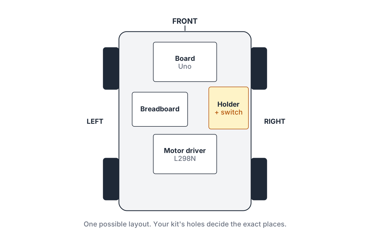
Put a small piece of tape on the front end and write FRONT. "Left" and "right" now mean the car's left and right, as if you sat in it facing the front.
Fix the motor driver, the board, the breadboard and the battery holder to the top plate, as in the figure. Use the kit's screws, or double-sided tape. Put the holder where you can reach its switch.
Fix the top plate onto the bottom plate. Bring all eight motor wires up so they reach the motor driver.
Screwing a wire into a terminal
Every motor wire ends in a small metal pin. It goes into a hole in the side of a screw block on the motor driver, and the screw on top clamps it. The same three moves work every time: loosen, push in, tighten. Then the tug test: pull the wire gently. If it comes out, it wasn't clamped.
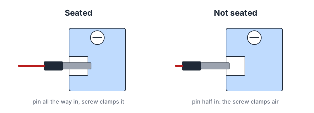
Left side. Turn both screws of the block marked OUT1 and OUT2 to the left a few turns, so the holes open.
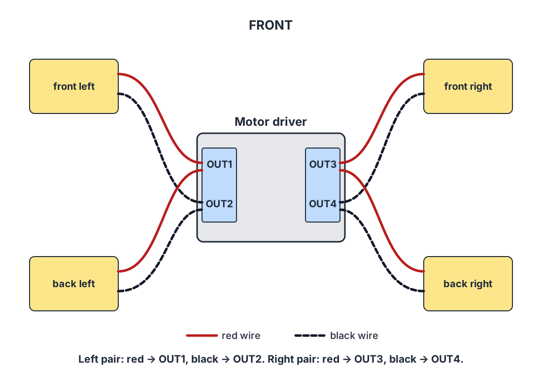
Push the red wires of both left motors into OUT1, side by side.
Push the black wires of both left motors into OUT2.
Tighten both screws, turning to the right until they're firm.
Tug each of the four wires gently. None should come out.
Check against the figure: both left motors, red in OUT1, black in OUT2.
Right side. Open both screws of the block marked OUT3 and OUT4.
Push the red wires of both right motors into OUT3.
Push the black wires of both right motors into OUT4.
Tighten both screws. Tug each of the four wires.
Check: both right motors, red in OUT3, black in OUT4 (the same figure as B12).
Test
You should see: all eight motor wires stay in when you tug them.
Instead: a wire slides out.
Meaning: the screw was clamping nothing, or only the plastic.
Fix: loosen that screw, push the metal pin in all the way, so no metal shows outside the hole, and tighten again. Tug again.
Where to go from here
Stage B is tested in Chapter 9: the wheels test →The chassis and its TT gear motors: ratings and wiring →Why swapping two motor wires reverses a wheel: the H-bridge lab →If the car doesn’t move: every symptom, its stage and its fix →The free book: Build a Car With Your Kid →