
Component
Chassis, Wheels and Gear Motors
The chassis is the part of the car a child actually points at. Four yellow gear motors bolt under a clear acrylic deck, each one carries a 65 mm rubber wheel, and everything else — board, driver, battery, buzzer — rides on top.
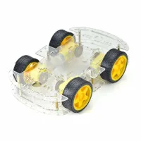
What is in the kit
- Two acrylic decks, both faces covered in a protective paper film. Peel it off before you build — until you do, the plastic looks scratched and cloudy, and people assume they were sent a damaged one.
- Four TT gear motors — the yellow plastic gearbox — with their wires already soldered on. That is the one purchase that decides whether you need a soldering iron for this build — motors sold with bare metal tabs instead of leads are the only part that would force one.
- Four 65 mm wheels with rubber tyres.
- Motor brackets, brass standoffs, bolts and nuts.
- Often a slotted encoder disc per motor. The car does not use them. They do no harm.
Buy the 4WD version — four motors, four wheels, two decks. The 2WD kit has two motors and a castor ball at the front, and the car sketch drives both of the L298N channels as if there were a pair of motors on each.
What the TT gear motor is rated for
- Operating voltage: 3V to 6V DC
- Gear ratio: 1:48
- No-load speed: about 200 rpm at 6V, about 90 rpm at 3V
- No-load current: about 150 mA
- Stall current: about 1.5 A at 6V (1.1 A at 3V)
- Shaft: 5.4 mm with two flats, which is the shape the wheel hub is cut for
Kits vary. Every seller ships the same yellow gearbox, but not always the same motor inside it. Treat these as the numbers to design around rather than a promise.
Why two motors share one channel
The L298N has two output channels and the car has four motors, so one side's pair of motors shares OUT1/OUT2 and the other side's pair shares OUT3/OUT4.
That is not a compromise. The car has no steering rack — it turns by driving one side forward while the other side goes back — so both wheels on a side always do the same thing anyway.
Each channel is good for 2 A. Two free-running TT motors draw about 300 mA between them, so there is a lot of headroom in normal driving. Two of them stalled at once — a wheel wedged against a chair leg — asks for around 3 A, past the channel's 2 A, and the L298N will get hot and eventually shut itself down to protect itself. Lift the car off the obstacle instead of letting it push.
What voltage the motors actually see
The L298N drops roughly 2V across its H-bridge. With the 7.4V battery pack the motors get about 5.4V, which sits neatly inside their 3V to 6V rating. This is the real reason the car uses a two-cell pack: three cells would be 11.1V, leaving about 9V across a motor rated for 6.
Getting all four wheels to turn the same way
A DC motor runs backwards when you swap its two wires, and the motors on the left of the chassis are physically mounted facing the opposite way to the ones on the right. So the wiring is not symmetrical: on one pair the wires cross over.
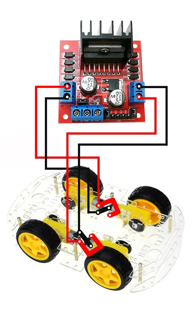
Wire it exactly as the diagram shows. If one wheel still spins against the others when you first drive it, swap that motor's two wires at the screw terminal — nothing else, and nothing in the code, needs to change.
Assembly notes
- Push the wheel onto the shaft by pressing on the hub, not by levering against the gearbox. The plastic gears inside are the weakest thing on the car.
- Route the motor wires up through the deck slots and away from the tyres. A wire that brushes a spinning wheel wears through in an afternoon.
- Do not overtighten the bracket bolts. The acrylic cracks around the hole long before the bolt gives.
- Leave the battery holder on the lower deck and the electronics on the upper one, so the heaviest part sits low.
Every part of the car
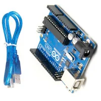 Arduino Uno R3: pins, power and limits
Brain
Arduino Uno R3: pins, power and limits
Brain
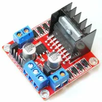 L298N motor driver with Arduino: pinout, wiring and code
Motion
L298N motor driver with Arduino: pinout, wiring and code
Motion
 HC-06 Bluetooth module for Arduino
Control
Chassis, Wheels and Gear Motors
You are here
HC-06 Bluetooth module for Arduino
Control
Chassis, Wheels and Gear Motors
You are here
 Buzzer
Sound
Buzzer
Sound
 18650 Lithium-Ion Batteries
Power
18650 Lithium-Ion Batteries
Power
 18650 Battery Holder
Power
18650 Battery Holder
Power
 18650 Battery Charger
Power
18650 Battery Charger
Power
 Jumper Wires and Circuit Wire
Wiring
Jumper Wires and Circuit Wire
Wiring
 Transparent Enclosure Box
Housing
Transparent Enclosure Box
Housing
Build it. Understand it.
Get the complete illustrated guide and start your first car — free.