
Build a Car With Your Kid · Chapter 10
Stage C: the resistors and the module wires
The video
The video of steps C1 to C9 isn’t filmed yet. It’s on its way, and it will go on this page: the QR in your book stays the same.
Until then, here are the wiring steps as Chapter 10 prints them. Each step names an exact breadboard hole, so go one at a time and check each against the figure.
Steps C1 to C8: the wiring
Warning
All power off before you start: type S, unplug the USB cable, and switch the battery holder off. The module's wires go near the board's 5V pin, and a slip with the power on can damage the module.
Check: the USB cable is out, and the holder's switch is off.
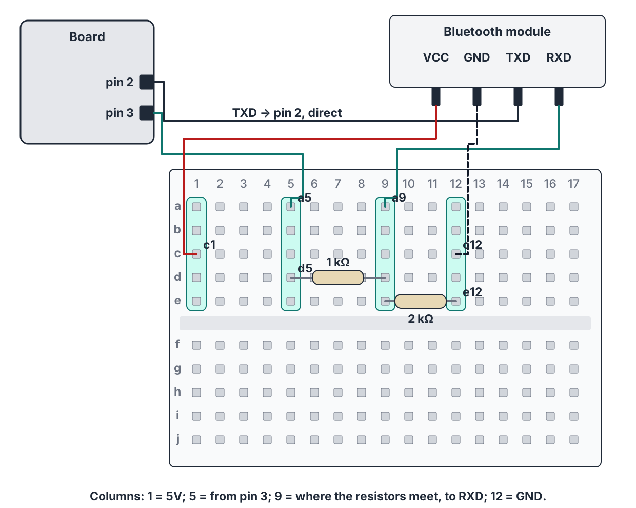
The 1 kΩ resistor (check its label): one leg in hole d5, the other in hole d9.
The 2 kΩ resistor (or the 2.2 kΩ): one leg in hole e9, the other in hole e12, the GND column.
With a male-to-male jumper: the board's pin 3 to hole a5.
With a male-to-female jumper: the module's VCC to hole c1, the 5V column.
With a male-to-female jumper: the module's GND to hole c12, the GND column.
With a male-to-female jumper: the module's TXD straight to the board's pin 2.
With a male-to-female jumper: the module's RXD to hole a9, the column where the two resistors meet.
Check, reading each line aloud while the child points (the figure is with C2 to C7):
- The 2 kΩ from e9 to e12. This is the only check it gets: no test can see it. The child points to both legs.
- 1 kΩ from d5 to d9.
- Pin 3 to a5.
- VCC to c1, GND to c12.
- TXD to pin 2.
- RXD to a9.
- Nothing from the module goes to pins 0 or 1.
Where to go from here
Next: tests C1 and C2, the module’s light and the phone connecting →Connecting the phone (HM-10 or HC-06) →The Bluetooth module: pins, voltages and the divider →If the car doesn’t move: every symptom, its stage and its fix →The free book: Build a Car With Your Kid →