
Datasheet
L298N datasheet: the ST L298 PDF, explained
The L298N datasheet is STMicroelectronics’ L298 document, DS0218 Rev 5, dated October 2023. It describes the bare chip: a dual full-bridge driver rated to 46V and 2A per channel. Download it below. The rest of this page pulls out the numbers that matter and shows how the chip’s pins map onto the red L298N module most people are actually holding, which the datasheet never mentions.
STMicroelectronics · DS0218 Rev 5 · 6 Oct 2023 · 23 pages
L298 — Dual full-bridge driver
The latest revision as of September 2026. Also on ST’s product page.
L298N specifications: the numbers that matter
| What | Value | Where |
|---|---|---|
| Motor supply, VS | up to 46V in operation; 50V absolute maximum | Table 4, Table 1 |
| Logic supply, VSS | 4.5–7V, 5V typical | Table 4 |
| Current per channel | 2A continuous; 2.5A repetitive; 3A for 100ms | Table 1 |
| Logic HIGH on IN/EN pins | 2.3V minimum, so a 3.3V board can drive it | Table 4 |
| Voltage lost in the driver | 1.8–3.2V at 1A; up to 4.9V at 2A | Table 4, VCEsat |
| Power dissipation | 25W, with the case held at 75°C | Table 1 |
| Idle current from VS | 13–50mA typical, 70mA maximum, with the bridge enabled and no load | Table 4 |
The module sets lower practical limits than the chip: its capacitors are rated 35V, and its onboard 5V regulator is only meant for supplies up to 12V. Both are covered further down.
L298 or L298N? The “N” is the package
There is one chip, the L298, in three packages. The ordering codes on page 18 of the datasheet:
| Order code | Package |
|---|---|
L298N | Multiwatt15, vertical leads: the one on the red module |
L298HN | Multiwatt15, horizontal |
L298P | PowerSO20, surface mount |
So “L298N datasheet” and “L298 datasheet” are the same document. The module took its name from the chip on it.
L298 chip pinout: pins 1–15, and where each lands on the module
The datasheet numbers the chip’s 15 pins. The module wires each one to a screw terminal or a header pin:
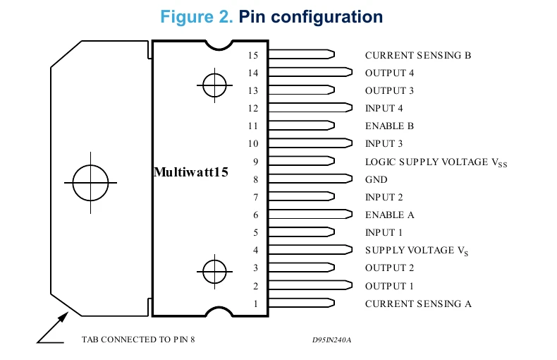
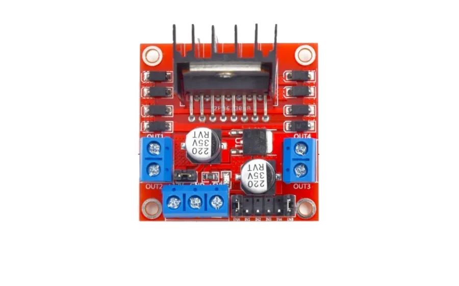
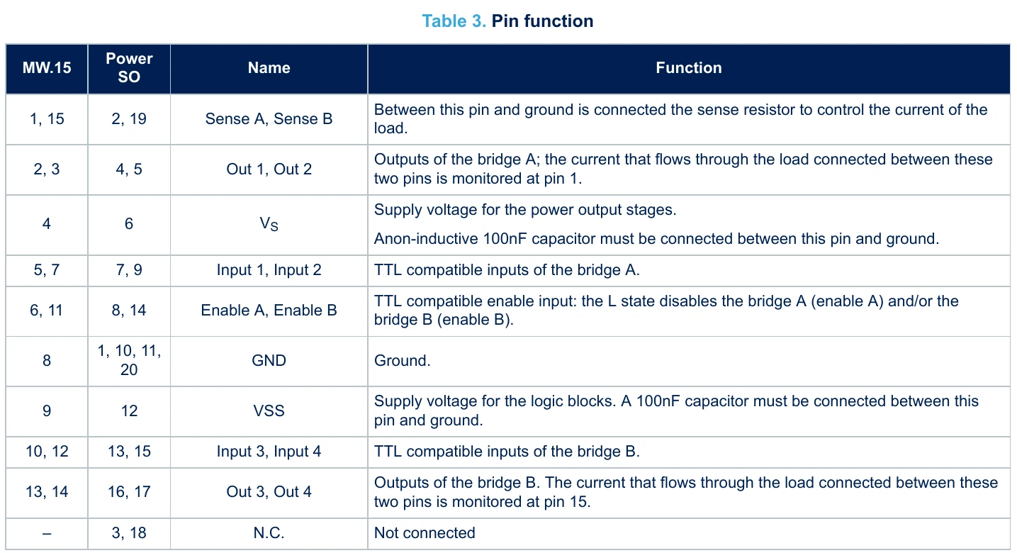
Two pins never reach you. SENSE A and SENSE B (pins 1 and 15) exist so a designer can put a small resistor there and measure motor current. The module ties both straight to GND, so there is no current sensing unless you modify the board.
Block diagram: two H-bridges
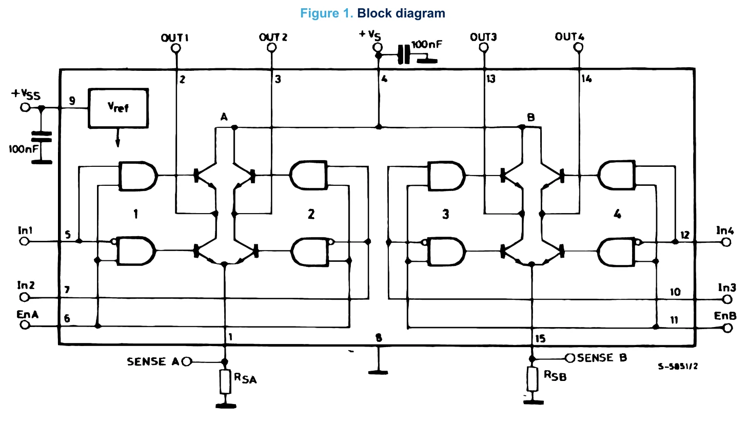
Each half is one H-bridge: four transistors with the motor across the middle. In1 and In2 pick which diagonal pair conducts, and EnA switches the whole bridge on or off. The motor driver page has the same bridge as a diagram you can tap through.
Absolute maximum ratings
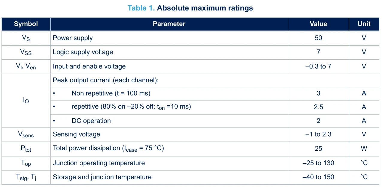
These are the lines past which the chip gets damaged, not targets to run at. The 3A figure is for 100 milliseconds, once; the number that matters for a motor that runs continuously is 2A per channel, and only with the heatsink doing its job.
Electrical characteristics
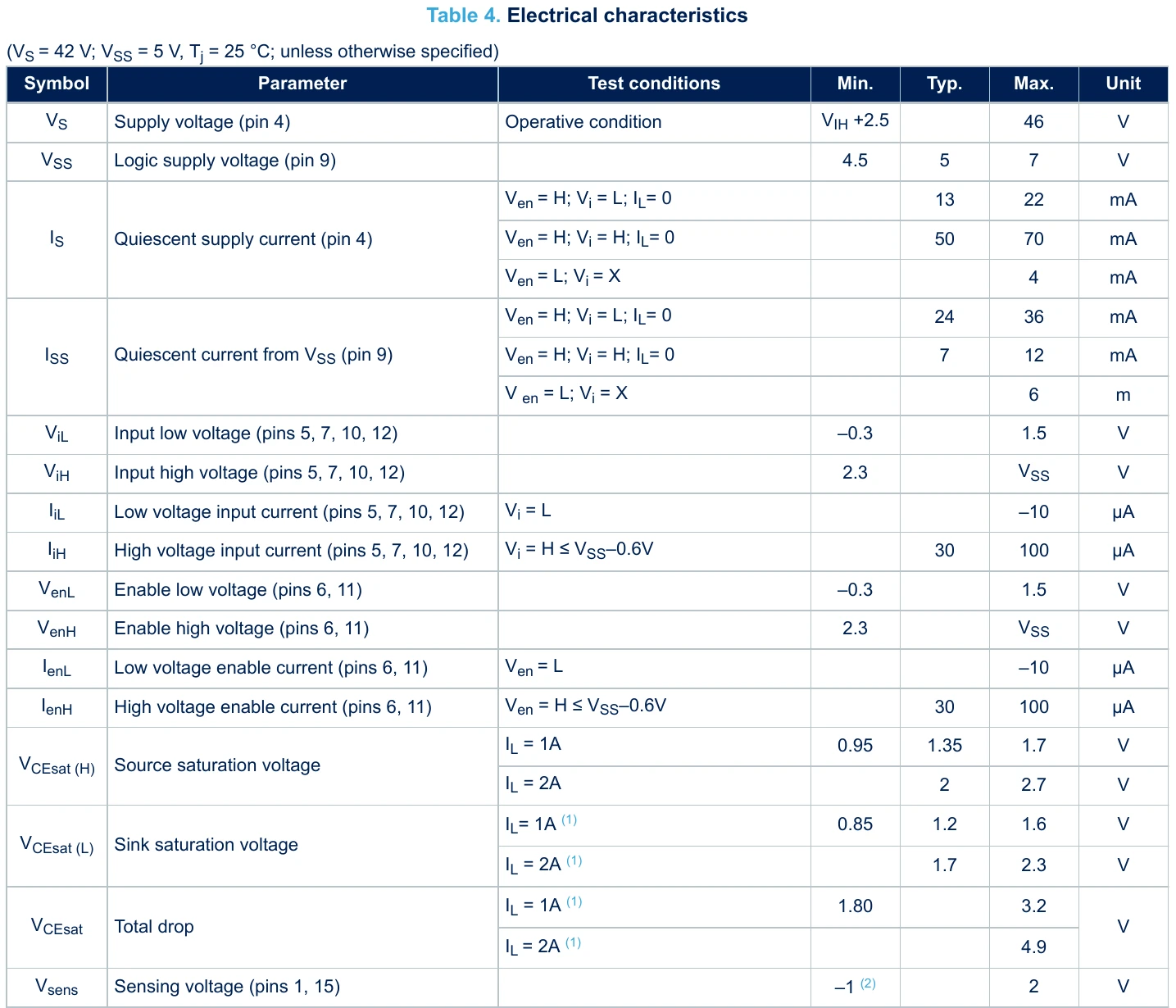
Three rows do most of the work:
ViH, input high voltage: 2.3V minimum. Anything above 2.3V counts as HIGH, so the 3.3V outputs of an ESP32 or a Raspberry Pi Pico drive the inputs directly. The chip’s own logic supply still needs 4.5V or more; on the module that comes from its regulator.VCEsat, total drop. The source and sink transistors each lose some voltage, and the motor sees what is left: 1.8–3.2V lost at 1A, up to 4.9V at 2A.IS, quiescent current. Up to 70mA from the motor supply with the bridges on and nothing moving. On a small battery that is not nothing.
L298N voltage drop: why the motors get less than the battery
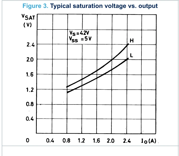
The two curves are the two transistors a current passes through, high side (H) and low side (L). Add them and you have the loss. The chart starts at 0.8A, where the pair already costs a little over 2V, and it only climbs from there. A pair of small gear motors draws well under an amp, below the chart’s range, so about 2V is an estimate rather than a reading, but a fair working figure, and it is why the Troniction car runs its motors from a 7.4V pack rather than a 6V one.
Driving a DC motor: figure 8 and table 5
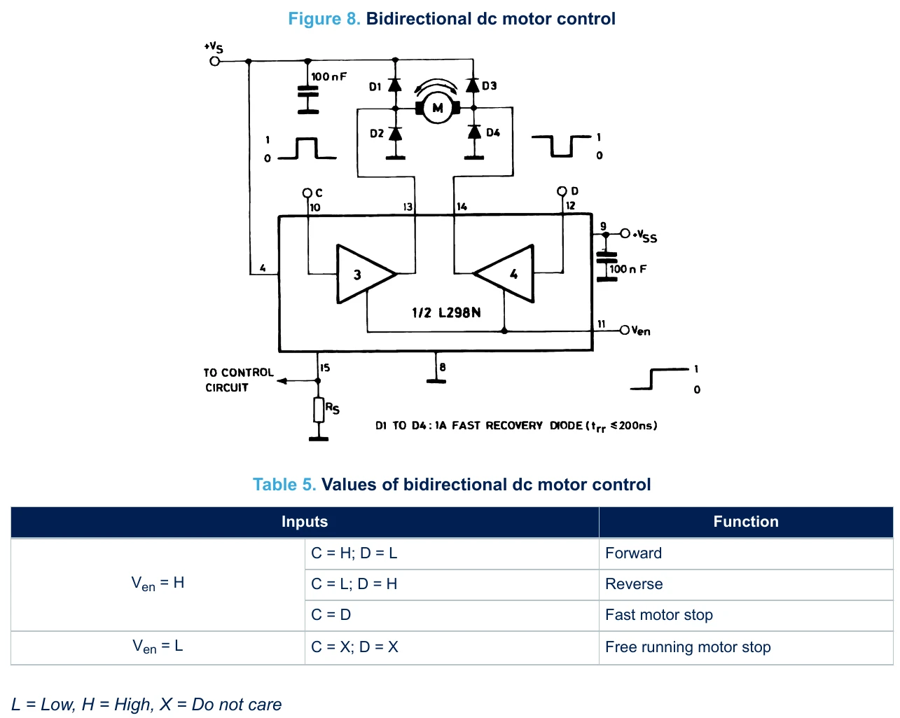
The figure draws bridge B: C and D are pins 10 and 12, which are IN3 and IN4 on the module, and Ven is pin 11, ENB. Bridge A works the same way with IN1, IN2 and ENA. The table says what the motor does: one input high and the other low turns it one way or the other; both the same brakes it fast; the enable low lets it coast. Note the four diodes, D1 to D4. The datasheet requires them, fast-recovery types, because a motor kicks back a voltage spike every time its current is switched off.
What the datasheet does not tell you: the module
Everything above is the chip. The red module adds six things, and they cause most of the questions. None of this is in ST’s datasheet; it comes from the board itself, and modules vary between makers, so check yours:
- Eight flyback diodes, marked
M7: the D1–D4 from figure 8, one set per bridge.M7is the common SMD marking for a 1N4007-type rectifier, a slower part than the fast-recovery diodes ST specifies. Fine for small hobby motors. - A 5V regulator, fed from
+12Vwhile the 5V-enable jumper is on. It powers the chip’s VSS and makes the+5Vterminal an output. Module makers say to take the jumper off above 12V and supply 5V yourself, because the regulator has to burn off the difference. - Two 220µF capacitors rated 35V, printed on their cans. That is why module listings say 35V, not the chip’s 46V.
- ENA and ENB jumper caps that tie the enables to 5V. With them on, the Arduino cannot control speed. Most wiring guides say to remove them; here is why.
- Sense pins tied to GND on the common board, so current sensing is not available without modifying it.
- Screw terminals for the motors and power, which is what keeps a build solder-free.
Which revision is this?
This is DS0218 Rev 5, dated 6 October 2023. Its revision history lists one change: an updated outline drawing for the horizontal package. We compared its ratings, input thresholds and saturation voltages with the January 2000 edition that still circulates, the copy this site hosted until 30 September 2026: they are the same. An older copy is not wrong, just older.
More datasheets
The datasheets index has the Arduino Uno’s ATmega328P and the HC-06 Bluetooth module. To wire the L298N into a working car, see the L298N motor driver page and step 2 of the build guide.
Common questions
- Where can I download the L298N datasheet?
- The official document is STMicroelectronics' L298 datasheet, DS0218 Rev 5 (October 2023). It is linked at the top of this page as a PDF and is also on ST's L298 product page. L298N is the vertical Multiwatt15 package of the L298, so it is the same datasheet.
- What is the difference between the L298 and the L298N?
- Only the package. L298N is the vertical Multiwatt15 package, L298HN the horizontal one, and L298P the PowerSO20 surface-mount version. The red L298N module uses the vertical L298N.
- What is the maximum voltage and current of the L298N?
- The chip runs up to 46V (50V absolute maximum) and 2A continuous per channel, with 3A allowed for 100 milliseconds. The common module is lower in practice: its capacitors are rated 35V, and its onboard 5V regulator is meant for supplies up to 12V.
- Can a 3.3V board like an ESP32 control an L298N?
- Yes. The datasheet's input high voltage is 2.3V minimum, so 3.3V logic reads as HIGH on the IN and EN pins. The chip's own logic supply still needs 4.5V to 7V, which the module's regulator or its +5V terminal provides.
- Why does the L298N lose about 2 volts?
- Current passes through two bipolar transistors in the bridge, and each drops some voltage. The datasheet gives a total drop of 1.8V to 3.2V at 1A and up to 4.9V at 2A, so the motors always see less than the supply.
Build it. Understand it.
Get the complete illustrated guide and start your first car — free.