
Component
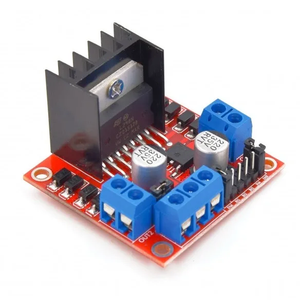
L298N motor driver for an Arduino car
The Arduino decides. The L298N does the pushing. It is the one part in this car that can be destroyed by a wiring mistake, and the one whose behaviour most often gets blamed on the code.
Why the car needs one at all
An Arduino pin can signal, but it cannot push. A pin supplies roughly 20 milliamps. One of the gear motors in this build wants a few hundred. Wire a motor straight to a pin and you do not get a slow car — you get a dead Arduino.
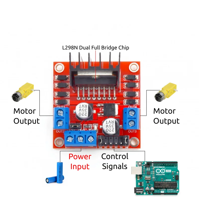
So the driver sits in between. The battery feeds it directly, and the Arduino only tells it which way and how hard, over six thin signal wires carrying almost no current at all.
How it works, in one paragraph
Inside each half of the board is an H-bridge: four switches arranged in a square with the motor across the middle. Close the top-left and bottom-right pair and current runs through the motor one way. Close the other diagonal and it runs the other way. That is the entire trick behind reverse, and it is why the board needs four control pins per side rather than one.
Wiring it to the Arduino
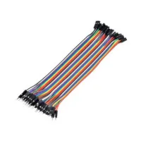
Six male-to-female jumper wires, straight across:
| Arduino pin | L298N pin | What it does |
|---|---|---|
5 | ENA | speed, left side |
6 | ENB | speed, right side |
9 | IN4 | direction |
10 | IN3 | |
11 | IN2 | |
12 | IN1 |
IN1–IN4 choose direction. ENA and ENB control speed, and they only work on Arduino pins that can do PWM — switching on and off fast enough that the motor averages it out. That is why they sit on pins 5 and 6 rather than anywhere convenient.
The two jumpers, and only one of them matters here
The board ships with small jumper caps on it, and they are not the same jumper. Confusing them is why speed control gets blamed on the sketch.
The ENA / ENB caps — pull these off. Most boards arrive with a cap bridging each enable pin to +5V. That ties the enables permanently high and overrides whatever the Arduino sends. Every speed then behaves as full speed, and no change to the code makes the slightest difference. On the reference car with both caps removed, speed 1 crawls and speed 9 runs — which is only possible with them off.
The 5V-enable jumper — leave this one alone. Different jumper, different job: it feeds the board’s onboard regulator from the main supply. It only has to come off when you power the board above 12V, at which point you supply 5V separately. This car runs on two 18650 cells, so it never gets near that. Leave it on.
Powering it
The battery holder’s red lead goes into +12V and black into GND, screwed down. Then the same two leads go across to the Arduino as well:
| Battery lead | L298N | Arduino |
|---|---|---|
| Red + | +12V | Vin |
| Black − | GND | GND |
That second pair does two jobs at once. It powers the Arduino, so the car does not die the moment you unplug the USB cable. And it gives the two boards a shared ground, which is what lets the driver understand the signals from the six wires above. Without it the wiring looks perfectly correct and nothing works.
Polarity destroys this board. Red to +12V, black to GND. The wrong way round kills the driver outright. Wire the battery last, every time, and check it twice — it is the only step in the whole build that can damage anything.
The 2V it takes for itself
An H-bridge is not free. The L298N drops roughly 2V across it, so the motors never see the full pack voltage — with the 7.4V pack in this build they get about 5.4V, which lands neatly inside the TT motors’ 3–6V rating.
That is the real reason this car uses a two-cell pack rather than three. Three 18650s would be 11.1V; take 2V off and the motors would still see around 9V, against a 6V rating. The chassis and gear motors page has the same arithmetic from the motor’s side.
An honest note about the battery
Two 18650 cells are 7.4V nominal, 8.4V fully charged. The Uno’s recommended Vin range is 7–12V, so this car spends its life at the very bottom of that range. It works — the reference car has run this way for years — but it means the Arduino browns out well before the cells are actually flat. If the car starts behaving strangely, charge it before you start debugging it.
Which one to buy
Get the screw-terminal version, around $8. That is the part that keeps this build solder-free: the motor leads and the battery leads land in the terminal block and are tightened with a small Phillips screwdriver. Boards sold without that block need an iron, and there is no soldering anywhere else in this car.
The numbers
From the manufacturer’s datasheet, for reference rather than reading:
| Spec | Value |
|---|---|
| Logic voltage | 5V |
| Drive voltage | 5V – 35V |
| Logic current | 0 – 36mA |
| Drive current | 2A max per bridge |
| Max power | 25W |
| Size / weight | 43 × 43 × 27mm, 30g |
Download the L298N datasheet if you want the manufacturer’s own document.
Where this fits
Three parts decide how this car behaves: the Arduino Uno makes the decisions, the L298N does the pushing, and the HC-06 listens to your phone. What it pushes is on the chassis and gear motors page, and what powers it on 18650 cells. The wiring itself is step 2 of the build guide; every part has a page, and the whole build is free to read.
Every part of the car
 Arduino Uno R3: pins, power and limits
Brain
Arduino Uno R3: pins, power and limits
Brain
 L298N motor driver for an Arduino car
You are here
L298N motor driver for an Arduino car
You are here
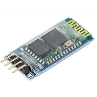 HC-06 Bluetooth module for Arduino
Control
HC-06 Bluetooth module for Arduino
Control
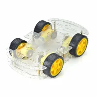 Chassis, Wheels and Gear Motors
Motion
Chassis, Wheels and Gear Motors
Motion
 Buzzer
Sound
Buzzer
Sound
 18650 Lithium-Ion Batteries
Power
18650 Lithium-Ion Batteries
Power
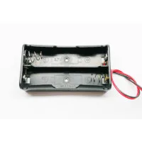 18650 Battery Holder
Power
18650 Battery Holder
Power
 18650 Battery Charger
Power
18650 Battery Charger
Power
 Jumper Wires and Circuit Wire
Wiring
Jumper Wires and Circuit Wire
Wiring
 Transparent Enclosure Box
Housing
Transparent Enclosure Box
Housing
Build it. Understand it.
Get the complete illustrated guide and start your first car — free.