
Build guide
Wire the Arduino car — no soldering
Five connections, none of them soldered. Every wire in this car either screws into a terminal block or pushes onto a header pin, and the whole thing takes an evening.
The order to do them in
- Motors → L298N
- L298N → Arduino
- HC-06 → Arduino
- Buzzer → Arduino
- Battery → L298N and Arduino — last, every time
Do them in that order. Leave the battery until the end: it is the only step that can damage anything, and there is no reason for the car to have power while you are still moving wires around.
The parts themselves are on the components pages if you want to know what each one does before you wire it.
Troniction Arduino Car Components
Refer to the following diagram to wire the components.
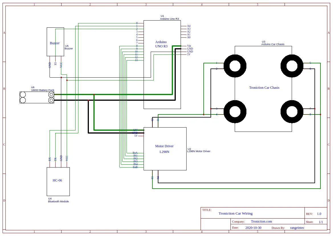
The enable pins in this diagram are out of date. It shows EnA on pin 13
and EnB on pin 8. The correct pins are 5 and 6 — 8 and 13 cannot do
PWM on an Uno, so the speed buttons would do nothing. See
the L298N wiring figure below, which is right.
Everything else in this diagram is correct.
Step By Step Walkthrough - Wiring the Troniction Arduino Car
- Connect Motor Driver L298N to Gear Motors L298N to Gear Motors
- Connect Motor Driver L298N to Arduino L298N to Arduino
- Connect Bluetooth Module HC-06 to Arduino HC-06 to Arduino
- Connect Buzzer to Arduino
- Connect Battery Pack to Arduino
Connect Motor Driver L298N to Gear Motors of the Chasis
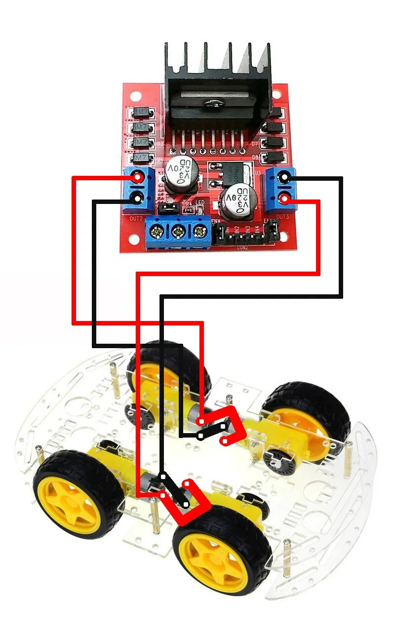
Tip: When the gear motor position changes direction perpendicularly, wires should also be interchanged to get the same rotating direction.
See the below diagram, same side wires are not parallel. The wires are interchanged. See the front two motor wirings, the wires are interchanged to get the same direction.
Warning: If you connect the wires parallelly and symmetrically then the wheels will rotate in opposite directions. You may have to change the wiring later.
Always connect the wires as shown in the diagram below. (Change the polarities of the wires when the gear motor rotates 90 degrees).
Connect Motor Driver L298N to Arduino
Connecting the motor driver L298N to Arduino is pretty straightforward. Just use a size 6 ribbon cable and connect the two as shown in the below table.
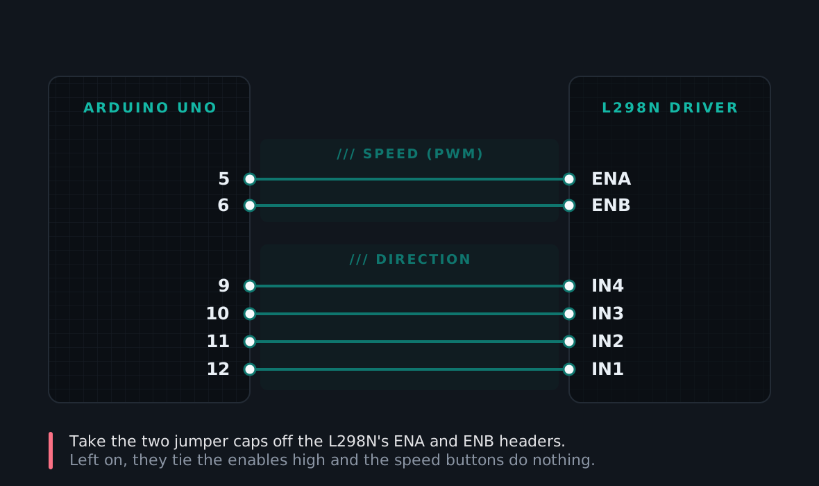
| Arduino Pin | L298N Pin |
|---|---|
5 |
EnA |
6 |
EnB |
9 |
IN4 |
10 |
IN3 |
11 |
IN2 |
12 |
IN1 |
Connect Bluetooth Module HC-06 to Arduino
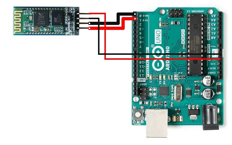
| HC-06 pin | Arduino pin | Note |
|---|---|---|
VCC | 5V | Not 3.3V — that rail is 50 mA for everything, and the module wants 40 while pairing |
GND | GND | |
TXD | 0 (RX) | crossed — see below |
RXD | 1 (TX) |
Why the wires cross. "Transmit" and "receive" are named from the point of view of whoever owns the pin. Two devices both talking on their TX line shout past each other, so the module’s talking pin has to land on the Arduino’s listening pin. Get it backwards and nothing breaks — the car simply never responds, which is the single most common way this build stalls.
Pins 0 and 1 are the same pins the USB cable uses to program the board. Unplug TXD and RXD before uploading a sketch and plug them back in after, or the upload fails with an avrdude error that explains nothing. The full explanation is here.
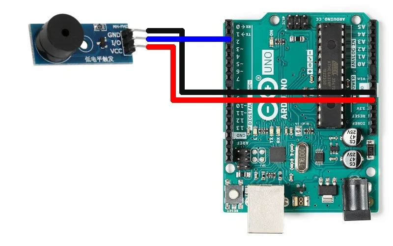
Connect Buzzer to Arduino
Signal pin to pin 2, plus power and ground. That is the whole connection. It handles the horn and the reversing beep, and plays Happy Birthday if you ask it to.
Connect Battery Pack to Arduino
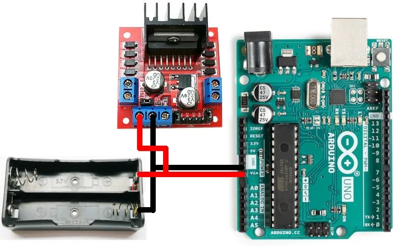
Two leads, but four connections — this is the step most often done half-way:
| Battery lead | L298N | Arduino |
|---|---|---|
| Red + | +12V | Vin |
| Black − | GND | GND |
That second pair does two jobs at once. It powers the Arduino, so the car does not die the moment you unplug the USB cable. And it gives the two boards a shared ground, which is what lets the driver understand the six signal wires at all. Skip it and the wiring looks perfectly correct while nothing works.
Polarity kills the driver. Red to +12V, black to GND. The wrong way round destroys the board outright. This is the only step in the build that can damage anything — which is exactly why it goes last.
Check these six before you power on
- Battery polarity — red to
+12V, black toGND. - No stray strands. Screw terminals fray wire ends, and one loose whisker touching its neighbour is a short.
- Grounds tied together — Arduino ground and driver ground must connect, or the signals have nothing to measure against.
- Nothing else on pins 0 or 1 if the HC-06 is there.
- All four motor wires seated and the screws actually tight. Tug each one gently.
- Car on a box, wheels off the ground for the first power-up.
Then connect the battery. Nothing should get warm. If anything does, disconnect it immediately and go back to point 1.
What is next
Wiring done, the car needs its sketch: step 4 is uploading the code, and the whole six-step guide is free to read.
Build it. Understand it.
Get the complete illustrated guide and start your first car — free.