
Datasheet
HC-06 datasheet: the module PDF, explained
The HC-06 datasheet is Guangzhou HC Information Technology’s module data sheet, revision 2.2 of April 2011. It describes the bare 27 × 13 mm module on a CSR BC417143 chip, powered at 3.1–4.2V, and its AT commands. Most HC-06s sold for Arduino are that module on a small 5V breakout board. The datasheet includes the maker’s own circuit for one, on page 11; this page shows it and maps the module’s pads onto the pins you hold.
Guangzhou HC (Wavesen) · Module data sheet Rev 2.2 · 6 Apr 2011 · 17 pages
HC-06 — Bluetooth serial module
The last revision in the document’s own history table. The maker trades as Wavesen; “linvor”, the name the module still answers to, is its former name.
Classic Bluetooth SPP — which is what an HC-05 and an HC-06 speak — is invisible to iOS at the operating-system level. No app fixes it, no library fixes it, and no wiring change fixes it. You need a BLE module: a genuine HM-10, or an ESP32. And Web Bluetooth is not the escape hatch — it is not in Safari, any version.
HC-06 specifications: the numbers that matter
| What | Value | Where |
|---|---|---|
| Bluetooth | 2.0 with EDR | page 9 |
| Chip | CSR BC417143B, with 8 Mbit of flash | pages 5, 9 |
| Supply, bare module | 3.1–4.2V; the VCC pad is 3.3V | pages 5, 6 |
| Current | 30–40mA while pairing; 8mA while communicating | page 5 |
| Transmit power | −4 to +6dBm, Bluetooth class 2 | page 5 |
| Receive sensitivity | −80dBm; −83dBm measured at <0.1% bit error rate | pages 5, 12 |
| Operating temperature | −25 to +75°C on page 5; −20 to +55°C on page 9 | pages 5, 9 |
| Size | 27 × 13 × 2mm | page 5 |
| Defaults | 9600 baud, 8N1; name linvor; PIN 1234 | page 15 |
Two things in that table deserve a flag. The two temperature ranges disagree, and the document does not say which wins; plan for the narrower one. And the 3.1–4.2V supply is the bare module’s. Seller listings that quote a range up to 6V are describing a breakout board’s regulator. The maker’s own adapter circuit feeds an R1114-33 3.3V regulator from 5V and gives no input range for it.
HC-06 pinout: the module and the breakout board
The datasheet labels its own photo with the pads that matter, numbered as on the module:
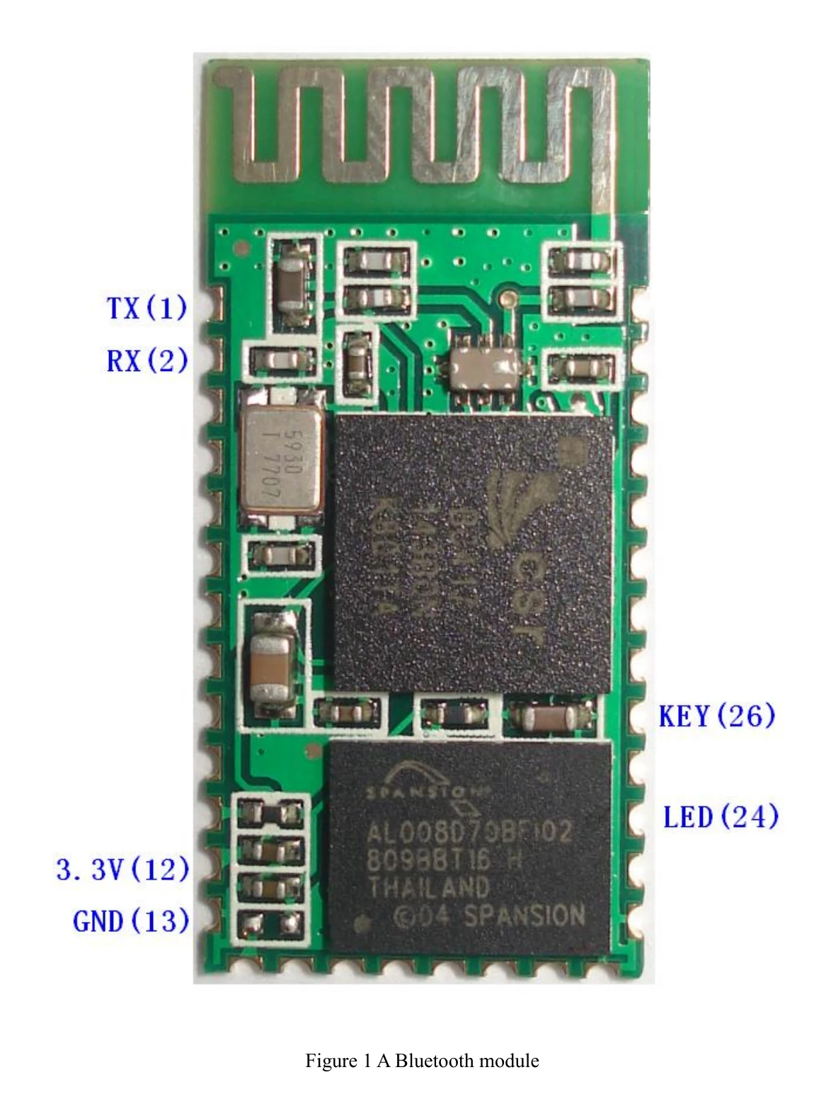
A breakout board brings four of them out to its header and puts a 3.3V regulator in front of the supply. The maker’s own adapter, further down, is wired like this:
| Breakout pin | Module pad | What it is |
|---|---|---|
VCC | 12, through the regulator | 3.3V supply; the regulator is why the board can sit on 5V |
GND | 13 (also 21, 22) | ground |
TXD | 1, UART_TX | the module talks: goes to the Arduino’s RX |
RXD | 2, UART_RX | the module listens: fed from the Arduino’s TX |
| LED on the board | 24, PIO1 | the status light, through a 470Ω resistor in the reference circuit |
The UART pads themselves are 3.3V CMOS, and the datasheet gives no 5V tolerance for them. The maker’s adapter protects its RX line with a diode, so the module never sees 5V. Retail boards vary, and you cannot tell from outside whether yours has that protection, so a 5V Arduino’s TX should reach RXD through a divider. The other direction needs nothing: 3.3V from the module clears the Uno’s HIGH threshold. The HC-06 module page has the divider and the reasoning.
HC-06 pad layout: all 34 pads
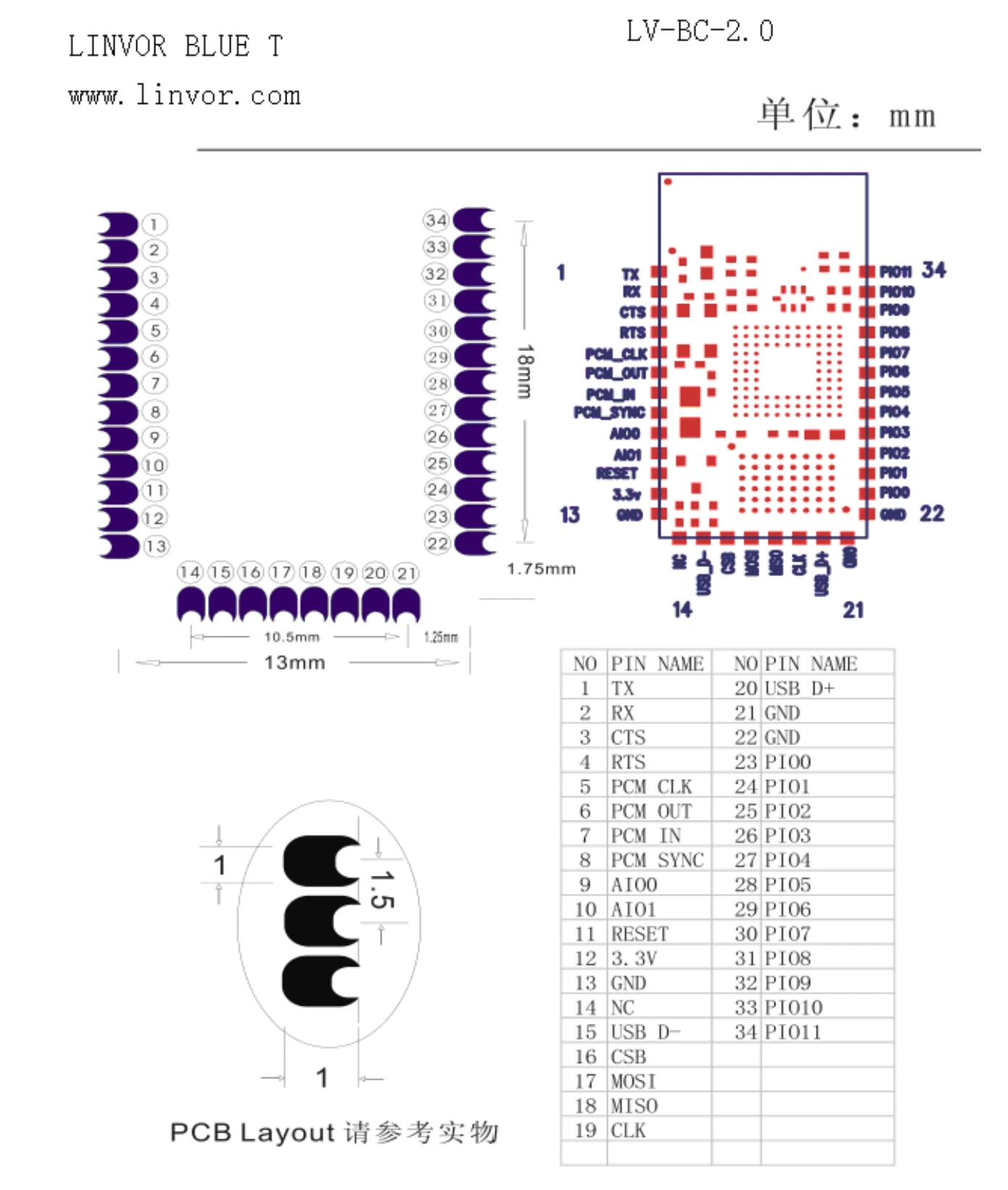
The pads are half-holes, made to be soldered flat onto another board. Beyond the four a breakout uses, the chip exposes flow control (CTS, RTS), PCM audio, USB, SPI for reprogramming, and twelve general-purpose pins. None of it is used in a serial-link project.
HC-06 reference circuits
Page 11 has two circuits. The first is an application example; the second is the maker’s own 5V adapter board, the closest thing in the document to the breakout most people hold.
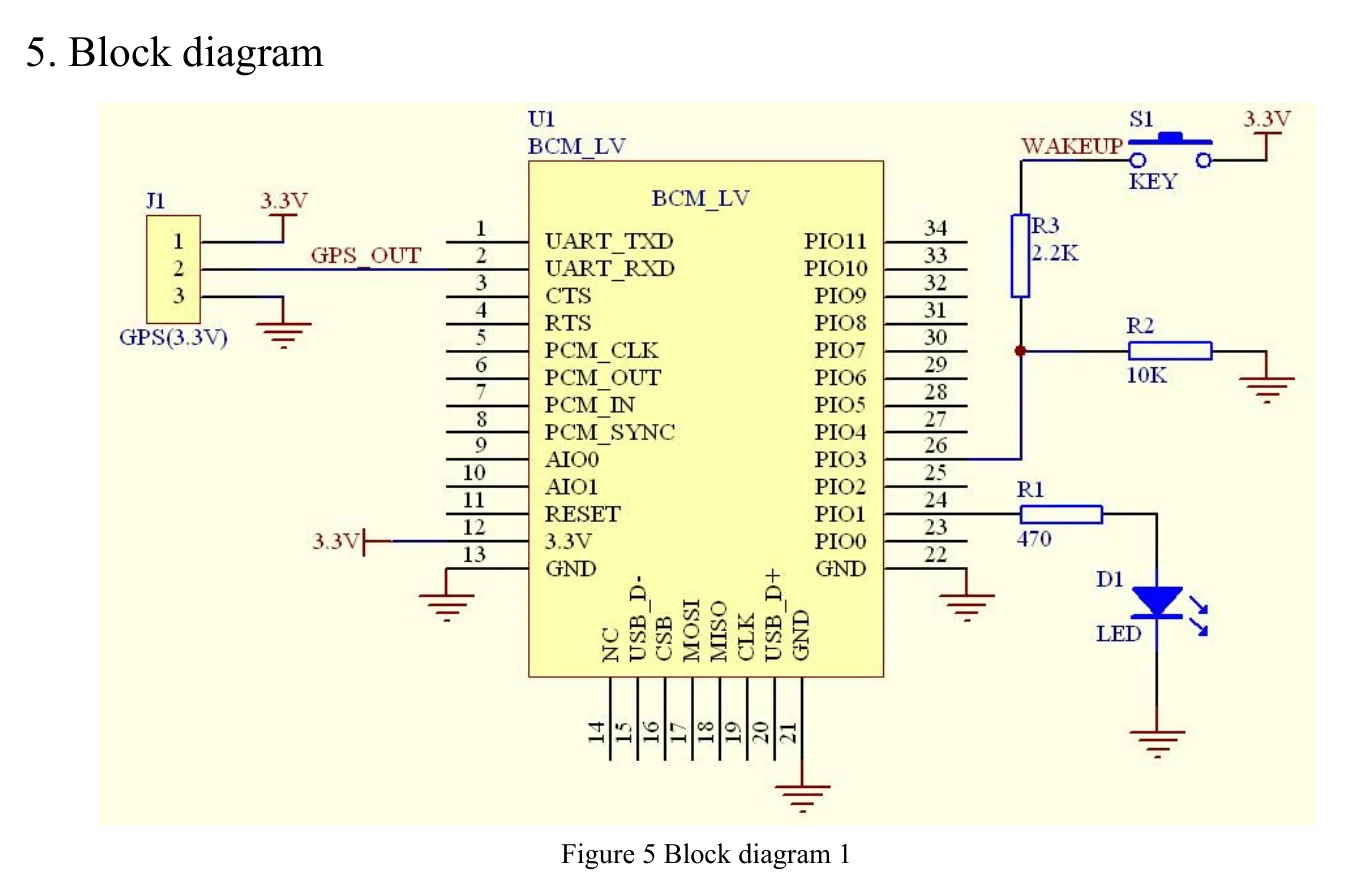
Block diagram 1 feeds a GPS receiver’s output into the module’s RX, puts the status LED on PIO1 (pad 24) through 470Ω, and a WAKEUP key on PIO3 (pad 26). Page 12 explains the key: on a master build, pressing it makes the module forget the last device it paired with.
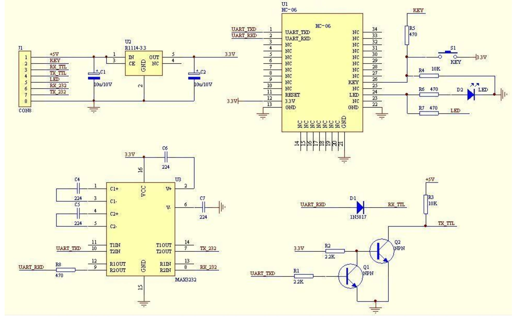
Block diagram 2 is the adapter board, and it answers the two questions that fill the forums:
- Power: 5V comes in on the header and an R1114-33 regulator makes the module’s 3.3V. That is why a breakout’s
VCCbelongs on the Arduino’s 5V pin. - Logic levels: 5V is never driven into the module.
RX_TTLreaches the module’s RX through a 1N5817 diode, and a pair of transistors lifts the module’s 3.3V TX up to 5V onTX_TTL. - Extras most retail boards leave out: a MAX3232 for real RS-232 levels, and a KEY input.
RF characteristics
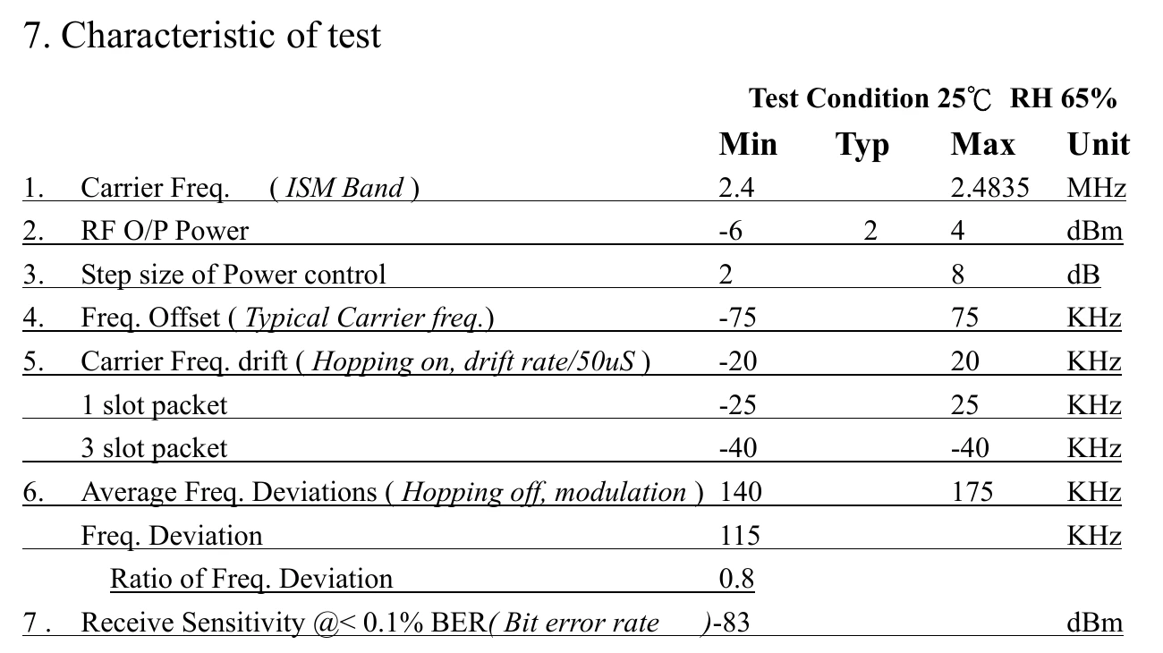
Output power of 2dBm typical and 4dBm at most puts it in Bluetooth class 2, the class usually quoted as about ten metres indoors. Note that this table tops out at 4dBm while the feature list on page 5 says 6. The document is not consistent with itself, which is typical of module datasheets and one more reason to test the range you actually need.
HC-06 AT commands, as the datasheet gives them
The module listens for commands whenever it is powered and not paired. The datasheet asks for about a second between commands, and the name, PIN and baud rate all survive a power cycle.
| Send | Datasheet reply | Does |
|---|---|---|
AT | OK | tests the link |
AT+BAUD4 | OK9600 | sets the baud rate: 1 = 1200, 2 = 2400, 3 = 4800, 4 = 9600, 5 = 19200, 6 = 38400, 7 = 57600, 8 = 115200, up to C = 1382400 |
AT+NAMEcarbot | OKname | renames it, up to 20 characters |
AT+PIN4321 | OKsetpin | sets the 4-digit pairing PIN |
AT+PN / AT+PO / AT+PE | OK NONE / OK ODD / OK EVEN | parity, on firmware above V1.5 |
AT+VERSION | LinvorV1.n | reports the firmware |
Do not set the baud above 115200 without a way back. The datasheet’s own note: a PC serial port cannot follow it higher, so the only route back down is a microcontroller programmed to talk at the new rate and send another AT+BAUD.
What the datasheet does not say is how to send them. There is no line ending, and no equals sign: AT+NAMEcarbot, never AT+NAME=carbot. Real linvor firmware also answers slightly differently from the table above, and some later boards sold as HC-06 run different firmware altogether. Why every AT command returns ERROR covers the Serial Monitor settings for each module and the test that tells you which firmware you have.
What the datasheet does not tell you
- Which board you have. The adapter circuit on page 11 is one design. Retail boards follow it more or less closely, and the datasheet cannot tell you which parts yours kept.
- What the LED means. On most boards, blinking means waiting for a connection and steady means connected. The datasheet only shows where it is wired.
- iPhones. The datasheet predates the question. The answer is in the box at the top of this page.
- Which role you have. The document covers master and slave builds. Modules sold for Arduino are the slave build: a phone or computer connects to them, never the other way round. For two Arduinos talking to each other, use an HC-05.
Which revision is this?
Its history table runs from version 1.0 in June 2006 to 2.2 on 6 April 2011, and the embedded Linvor specification sheet is dated September 2006. It is an old document for an old design. As far as we know no later revision exists: the maker moved on to newer modules rather than updating this one.
More datasheets
The datasheets index has the L298N motor driver, explained, and the Arduino Uno’s ATmega328P. For the link itself failing, not the part, see the Arduino Bluetooth symptom index.
Common questions
- Where can I download the HC-06 datasheet?
- The HC-06 module data sheet from Guangzhou HC Information Technology, revision 2.2 of April 2011, is linked at the top of this page as a 17-page PDF. It is the maker's own document; the company trades as Wavesen, and linvor, the default module name, is its former name.
- What are the HC-06 default name, PIN and baud rate?
- The datasheet gives name linvor, PIN 1234 and 9600 baud, 8 data bits, no parity, 1 stop bit. All three can be changed with AT commands while the module is not paired: AT+NAME, AT+PIN and AT+BAUD, with no equals sign and no line ending.
- Can I power the HC-06 from 5V?
- The bare module runs at 3.1 to 4.2V, but the breakout board most people use has a 3.3V regulator, so its VCC pin can go on the Arduino's 5V. The regulator does not protect the data pins: fit a divider between the Arduino's TX and the module's RXD.
- Does the HC-06 work with an iPhone?
- No. Classic Bluetooth SPP — which is what an HC-05 and an HC-06 speak — is invisible to iOS at the operating-system level. No app fixes it, no library fixes it, and no wiring change fixes it. You need a BLE module: a genuine HM-10, or an ESP32. And Web Bluetooth is not the escape hatch — it is not in Safari, any version.
- What chip is inside the HC-06?
- A CSR BC417143B with 8 Mbit of external flash, running Bluetooth 2.0 with EDR, according to page 9 of the datasheet. The flash holds the firmware, which is why modules with the same hardware can answer different AT commands.
Build it. Understand it.
Get the complete illustrated guide and start your first car — free.