
Learn
Which pins for a Bluetooth module on each board — Uno, Nano, Mega, Leonardo, Uno R4 and ESP32
Troniction
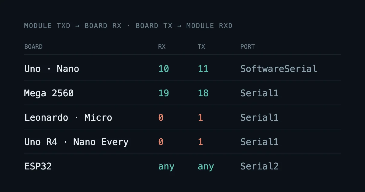
On an Uno or a classic Nano, the module goes on SoftwareSerial pins 10 and 11. On a Mega it goes on Serial1: module TXD to pin 19, pin 18 through the divider to the module's RXD. On a Leonardo, Micro, Uno R4 or Nano Every it goes on Serial1, which is pins 0 and 1. On an original ESP32 it goes on any free GPIO you name in Serial2.begin(), with no divider. The rule under all of it: if the board has a second hardware serial port, use it.
Most HC-05 and HC-06 tutorials are written for an Uno. Move one to another board and the wiring copies across fine, but the pin numbers often don't, and sometimes the result compiles, sends, and never receives. This page is the table I use, and the two traps that catch people.
The one question that decides it
Before you look at pin numbers, ask: does this board have a second hardware serial port?
An Uno has one hardware serial port, Serial, and it's already taken. It's the line from the USB chip to pins 0 and 1, used for uploads and the Serial Monitor. That's why every Uno tutorial reaches for SoftwareSerial: there's nothing else to use. SoftwareSerial works, but it has limits, and they are the reason the next board up is easier.
If your board has a second port, the module gets a real piece of hardware to itself, and none of SoftwareSerial's limits apply. SoftwareSerial vs hardware serial explains the difference properly; for wiring, the table is enough.
The table
| Board | Module TXD goes to (board RX) | Board TX goes to the module's RXD | In the sketch |
|---|---|---|---|
| Uno R3, Nano (classic) | 10 | 11, through the divider | SoftwareSerial bt(10, 11) |
| Mega 2560 | 19 (RX1) | 18 (TX1), through the divider | Serial1 |
| Leonardo, Micro | 0 (RX1) | 1 (TX1), through the divider | Serial1 |
| Uno R4 Minima, Uno R4 WiFi | 0 | 1, through the divider | Serial1 |
| Nano Every | 0 (D0) | 1 (D1), through the divider | Serial1 |
| ESP32 (original) | any free GPIO you choose | any free GPIO you choose, direct | Serial2 |
Checked against Arduino's and Espressif's documentation on 2026-10-01. The direction never changes: module TXD goes to the board's RX, and the board's TX goes to the module's RXD. Two outputs facing each other is the most common wiring fault there is, and it's the same mistake on every board.
The divider is the same on every 5 V board
Every board in the table except the ESP32 drives its pins at 5 V. The module's RXD is a 3.3 V input. So the rule from the Uno holds unchanged: the board's TX goes through a 1 kΩ / 2 kΩ divider to the module's RXD, and the module's TXD goes straight to the board's RX. Only the pin numbers move. If you haven't wired one before, the HC-05 voltage divider shows why it's only on one wire.
Trap one: pins 0 and 1 mean opposite things
This is the trap that makes a correct wiring look wrong.
On an Uno, a classic Nano or a Mega, pins 0 and 1 are the USB port's serial line. Put the module there and it shares a wire with the USB chip. Uploads fail or hang while the module is connected, and the Serial Monitor sees the module's traffic mixed with yours. That's why the advice "never use pins 0 and 1" exists, and on those boards it's good advice. Why the upload hangs with Bluetooth connected has the whole story.
On a Leonardo, Micro, Uno R4 or Nano Every, USB is separate. On the Leonardo and the Micro, the chip itself does USB, and Serial is that USB link. On the Uno R4 and the Nano Every, Serial is also the USB connection, kept apart from the pins. On all four, pins 0 and 1 are Serial1, a hardware port that nothing else uses. That's exactly where the module should go.
So the same advice is right on one board and wrong on the next. A Leonardo owner who moves the module off 0 and 1 "to be safe" has moved it off the best pins on the board.
Trap two: SoftwareSerial can't receive on every pin
On the Uno and the classic Nano, SoftwareSerial can receive on any digital pin except 0 and 1. On the Mega and the Leonardo it can't.
SoftwareSerial receives by watching for the start of each byte with a pin-change interrupt. On the Uno's chip, every pin has one. On the Mega's and the Leonardo's chips, only some pins do. Put the receive pin anywhere else and the sketch compiles, sends perfectly, and never receives a thing. Nothing tells you why.
| Board | Pins that can be the SoftwareSerial RX |
|---|---|
| Mega, Mega 2560 | 10, 11, 12, 13, 14, 15, 50, 51, 52, 53, A8 (62) to A15 (69) |
| Leonardo, Micro | 8, 9, 10, 11, 14 (MISO), 15 (SCK), 16 (MOSI) |
| Uno, Nano (classic) | any digital pin, but not 0 or 1 |
From Arduino's SoftwareSerial reference, checked 2026-10-01.
Notice that pin 10 is on every list. So SoftwareSerial bt(10, 11) works on all three families, which is why I use 10 and 11 on the Uno in the first place. An Uno tutorial with the RX on pin 2, moved to a Mega, is the classic case of "it sends but nothing comes back".
Two more limits apply on every board. SoftwareSerial can't send and receive at the same time, and if you create two SoftwareSerial ports, only one listens at a time. On a board with Serial1, the answer to all of this is simply not to use SoftwareSerial.
The sketch for a board with Serial1
On a Mega, Leonardo, Micro, Uno R4 or Nano Every, this is the test I run first. It passes everything you type in the Serial Monitor to the module, and everything the module receives back to the Serial Monitor. If letters cross both ways between the phone app and the monitor, the wiring is right.
const long BT_BAUD = 9600;   // 38400 for an HC-05 in AT mode

void setup() {
  Serial.begin(9600);
  Serial1.begin(BT_BAUD);
  while (!Serial) { }  // Leonardo/Micro: wait for monitor
  Serial.println(F("Serial1 bridge ready. Type above."));
}

void loop() {
  // module -> screen
  if (Serial1.available()) Serial.write(Serial1.read());
  // screen -> module
  if (Serial.available())  Serial1.write(Serial.read());
}
How far it's been checked: this compiles for the Mega, the Leonardo and the Micro with arduino-cli (arduino:avr 1.8.8, 2026-10-01). I haven't run it on those boards, and I haven't compiled it for the Uno R4 or the Nano Every.
The while (!Serial) line matters on the Leonardo and the Micro: their USB link takes a moment to come up, and without it the ready line can print before the monitor is listening.
If the ready line prints but nothing arrives from the phone
On a Mega with the module on 19 and 18, the usual cause is the module's TXD on 18 (TX1) instead of 19 (RX1). Two outputs face each other, and nothing gets through. Swap the two data wires. The divider stays on whichever wire comes from the board's TX. If the wires are right and it's still silent, connected, but no data goes through the other causes in order.
The ESP32: 3.3 V, and name your pins
The ESP32 is different in two ways.
It's a 3.3 V board. The module's serial pins are 3.3 V too, so the two connect directly, with no divider. But nothing 5 V may drive an ESP32 input: the datasheet rates its inputs to the supply plus 0.3 V, about 3.6 V.
Name the pins. The ESP32 can put a hardware serial port on almost any GPIO, so I always say which ones in the sketch:
Serial2.begin(9600, SERIAL_8N1, RX_PIN, TX_PIN);
Don't rely on the default pins. They changed between versions of the ESP32 Arduino core: in core 2.x, Serial2 defaulted to GPIO16 and 17; in 3.0 it moved to GPIO4 and 25. A tutorial written for one core is wired wrong for the other.
Three groups of pins to avoid:
- GPIO 6 to 11: used by the board's flash memory.
- GPIO 16 and 17: used by flash or PSRAM on some modules.
- GPIO 34 to 39: input only. Fine for RX, never for TX.
Most of the time, though, an original ESP32 doesn't need an external module at all: it has Classic Bluetooth and BLE on the chip. Whether to use one instead of an Uno and a module is a bigger question, with its own answer.
Boards with Bluetooth built in
Some boards need no module, so there are no module pins to choose:
- Nano 33 BLE: BLE only, 3.3 V, and Arduino's own page says its pins are not 5 V tolerant.
- Nano ESP32: built on the ESP32-S3, which has BLE and no Classic Bluetooth.
- Original ESP32 boards: Classic and BLE.
BLE-only boards behave like an HM-10 from the phone's side, not like an HC-05 or HC-06. The apps that talk to an HC-06 won't see them. If you're still choosing a module, HC-05 vs HC-06 vs HM-10 is where that decision lives.
The short version
- Uno, classic Nano: SoftwareSerial on 10 (RX) and 11 (TX), divider on 11.
- Mega:
Serial1, 19 (RX1) and 18 (TX1), divider on 18. If you must use SoftwareSerial, RX on 10 to 15, 50 to 53, or A8 to A15. - Leonardo, Micro, Uno R4, Nano Every:
Serial1on 0 (RX) and 1 (TX), divider on 1. Here, pins 0 and 1 are the right pins. - ESP32:
Serial2on GPIOs you name, no divider, never 5 V on an input.
On every board, module TXD goes to the board's RX. If the wiring is right and you still see nothing, the next places to look are all the fixes, by symptom.
Common questions
- Which pins do I use for an HC-05 on an Arduino Mega?
- Use the Mega's second hardware port. The module's TXD goes to pin 19 (RX1), and pin 18 (TX1) goes through the 1 kΩ / 2 kΩ divider to the module's RXD. In the sketch it is Serial1, so there is no SoftwareSerial at all and the USB port keeps Serial.
- Can I put the Bluetooth module on pins 0 and 1?
- It depends on the board. On an Uno, a classic Nano or a Mega, pins 0 and 1 are the USB port's serial line, and a module there gets in the way of uploads. On a Leonardo, Micro, Uno R4 or Nano Every, USB is separate, and pins 0 and 1 are Serial1, the right place for the module.
- Why does my module receive nothing on a Mega with SoftwareSerial on pin 2?
- SoftwareSerial can only receive on a pin with a pin-change interrupt, and pin 2 on a Mega has none. The sketch compiles and sends, but never receives. On a Mega, use Serial1 on pins 19 and 18 instead, or a SoftwareSerial RX pin from the list: 10 to 15, 50 to 53, or A8 to A15.
- Does an ESP32 need a voltage divider for an HC-05?
- No. The ESP32 and the module's serial pins are both 3.3 V, so the two connect directly. The divider only comes back when something 5 V drives an ESP32 input, because the datasheet rates its inputs to about 3.6 V.
Still not connecting?
Arduino Bluetooth — Make It Connect is a 277-page book of every way the link fails, why, and the fix — HC-05, HC-06 and HM-10 BLE, including the clone family few sources cover. PDF and EPUB, $15.